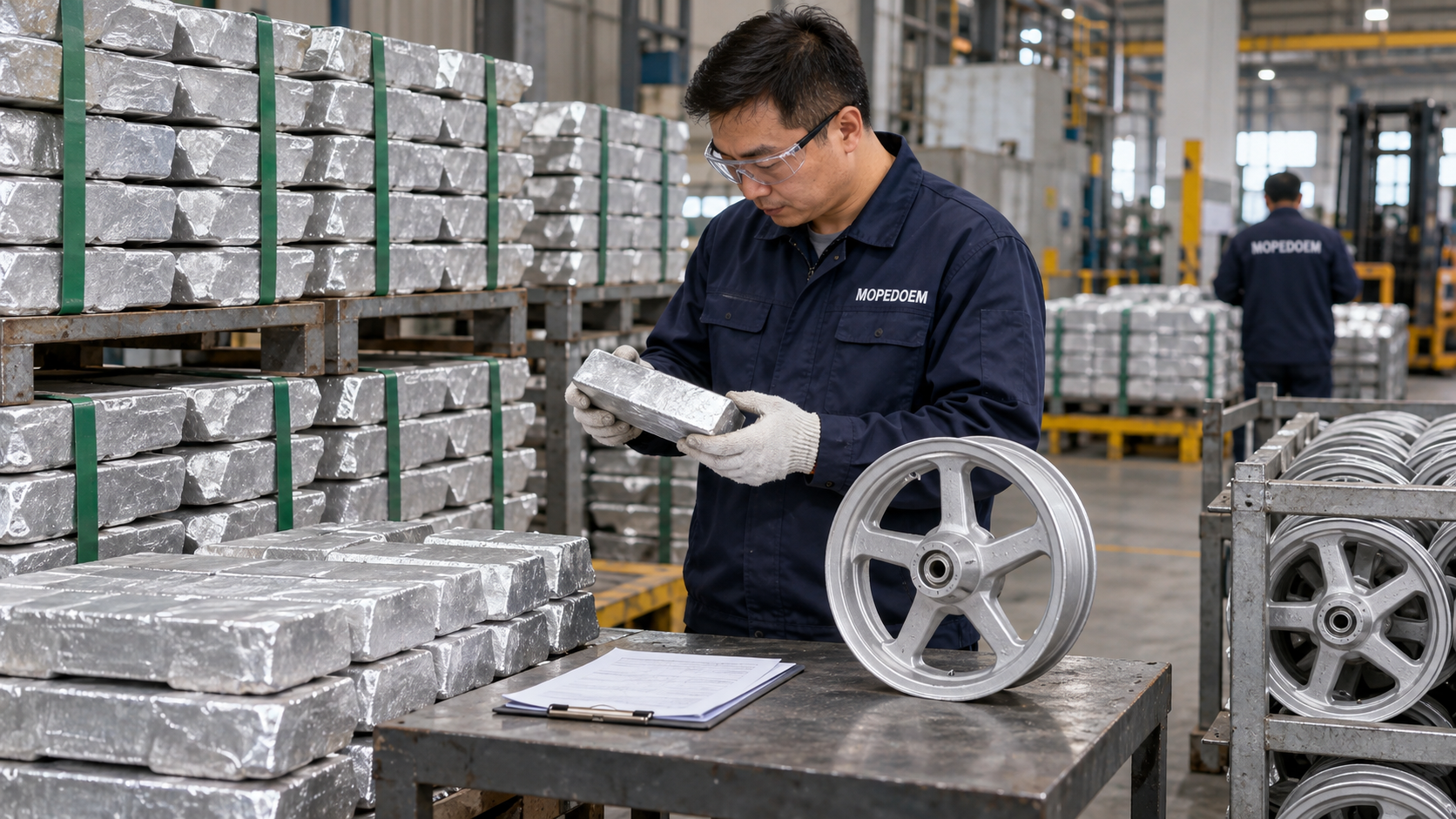
Choose a stage to enter its chapter. Every image is an AI-generated photographic-style illustration; process parameters follow the actual work instructions.
Written process guide
Generic process illustrations, not evidence of a factory owned by our company. Actual work instructions and acceptance requirements must be confirmed for the order.
Aluminum Receiving and Charge Preparation
Check the alloy grade, material condition, and lot. Do not mix different aluminum stocks as if they shared one recipe.
- Check the material quality documents, grade, and work order. Use remelt stock only according to the approved charge rules.
- Check for contamination, mixed materials, and stock unsuitable for charging. Segregate any exceptions.
- Weigh and label the charge against the charge sheet, link it to the melt lot, and send it to the designated furnace group.
Melting, Refining, and Degassing
Melt, refine, degas, and inspect the melt according to the alloy and site process.
- Use the appropriate furnace and protective measures. Melt to the procedure and verify composition and material condition.
- Remove inclusions and gas using the validated process. Prevent contamination and uncontrolled transfers.
- Record the melt checks and furnace lot. Once casting conditions are met, transfer to holding or metal delivery.
Low-Pressure Casting
This route illustrates a one-piece low-pressure casting. Casting conditions depend on the die and alloy process.
- Check the die, coating, equipment guarding, and process revision. Prepare the die and metal supply as specified.
- Follow the validated low-pressure casting cycle for filling, holding pressure, and controlling solidification to manage defect risk.
- Open the die when the specified removal condition is reached and extract the wheel blank with suitable tooling.
Cooling, Gate Removal, and Trimming
Cool as specified and remove gates, risers, and flash while protecting the rim and spokes.
- Cool the blank to the procedure, retain its lot identification, and confirm it is ready for cutting and trimming.
- Support the casting with tooling while cutting off gates and risers. Do not arbitrarily remove material from load-bearing features.
- Remove flash and trim eligible edges. Segregate the offcuts and check the casting for damage.
Internal Casting and Nondestructive Inspection
Use suitable methods such as radiography, as required by the inspection plan, to look for internal casting defects.
- Verify the inspection locations, method, scope, equipment condition, and acceptance criteria.
- Inspect with the appropriate shielding and working conditions. Keep records linked to the corresponding wheel blank.
- Segregate and disposition nonconforming blanks. Release conforming blanks to the next specified operation.
Heat Treatment (as Required by the Alloy)
This route illustrates a cast aluminum wheel requiring heat treatment. The actual cycle depends on the alloy and product design.
- Verify the alloy, heat treatment requirements, lot, and loading method. Do not apply the same cycle to every aluminum wheel.
- Where solution treatment, quenching, or aging is required, follow the corresponding validated cycle and sequence.
- Record the furnace lot and check material condition, performance, and distortion as required. Release the blanks to machining.
CNC Machining
Machine the rim, bearing bores, and specified mounting interfaces to the drawing, using consistent locating datums.
- Check the blank, fixture, and program revision. Locate as specified and avoid clamp marks and distortion.
- Machine the rim and functional interfaces with the approved program. Protect sealing and assembly surfaces.
- Remove chips, recheck critical dimensions and surface condition, and record first-piece and in-process inspections.
Deburring, Dimensional and Structural Inspection
Remove machining burrs and check dimensions and runout. Schedule leak testing and similar checks according to the construction and inspection plan.
- Deburr openings and edges and remove debris without damaging machined functional surfaces.
- Check critical dimensions and radial and axial runout from the specified datums. Link the results to the machining lot.
- Check tubeless sealing designs for airtightness as required. Verify strength, impact, and fatigue separately under the product plan.
Cleaning and Degreasing Before Painting
Clean and degrease according to the substrate and contamination. Use suitable processes and lot controls for aluminum and steel separately.
- Verify the substrate, surface condition, and paint work order. Confirm release from prior machining and structural inspection.
- Clean and degrease using a process suitable for aluminum alloy. Avoid excessive attack or contamination of functional surfaces.
- Rinse and confirm cleanliness as specified. Prevent liquid carryover, retained debris, and recontamination.
Conversion Treatment, Rinsing, and Drying
Select the conversion system for the substrate and paint system. Aluminum and steel wheels need not use the same bath chemistry.
- Confirm that the pretreatment is compatible with aluminum alloy and the subsequent liquid coating. Do not simply reuse the steel formula.
- Treat and rinse to the validated procedure. Control residue and cross-contamination between baths.
- Dry as specified and transfer promptly. Check the surface condition and readiness for coating adhesion.
Masking Functional Surfaces and Applying Liquid Primer
Mask bearing bores and designated mating surfaces to the drawing and use a compatible liquid primer.
- Fit masking and fixtures as the product requires. Do not designate every rim surface as a no-spray area by default.
- Check the primer, mix ratio, and working life. Apply it evenly in a suitable booth using the validated process.
- Complete the specified flash-off or intermediate drying and meet the required conditions before topcoating.
Topcoat Mixing and Application
This example shows a graphite-black liquid topcoat. Confirm the color, number of coats, and any additional layers with the customer's paint system.
- Verify the color sample, primer and topcoat compatibility, material lots, mixing instructions, and working life.
- Spray the rim, spokes, and designated areas to the procedure. Control edge coverage, paint buildup, and missed areas.
- Inspect appearance and complete the specified flash-off. If an extra clearcoat or similar layer is required, follow the approved intercoat and cure procedure in full.
Oven Drying, Curing, and Cooling
Set curing conditions for compatibility with the substrate, heat-treated condition, and all coating layers.
- Check coating condition, spacing between hung parts, the work order, and the applicable oven program.
- Follow the validated coating cure while respecting the aluminum wheel's material condition and allowable thermal history.
- Once the part has reached the specified post-treatment condition and cooled, remove temporary protection as required and send it for inspection.
Coating, Appearance, and Final Inspection
Recheck appearance, functional interfaces, and coating records. Carry out specified performance checks according to the inspection plan.
- Check color, gloss, particles, runs, missed coverage, masking boundaries, and mating surfaces.
- Measure coating thickness and perform specified adhesion, corrosion, and other checks to plan. Use designated coupons or samples for destructive tests.
- Check previous structural and dimensional records, the paint lot, and closure of exceptions. Segregate and reinspect nonconforming parts as required.
Protective Packing and Handover
Protect each wheel, keeping model, substrate, color, and lot identifiable. Send it to the relevant wheel or vehicle assembly operation.
- Verify release, model, material route, color, quantity, and order requirements.
- Use clean, soft wrapping and separators to protect the finish and functional interfaces from contact damage.
- Link carton IDs to lots and hand over against the order. Schedule later fitting of bearings, tires, or motors according to the actual construction.
Steel Receiving and Blank Preparation
This route uses stamped and welded steel construction. Prepare rim, wheel disc, and matching hub components separately.
- Verify steel grade, thickness, condition, and the work order. Do not reuse car or truck wheel dimensions.
- Prepare rim strip, disc stamping blanks, and hub parts separately to the procedure and control edge quality.
- Check appearance, specifications, and quantities, and keep each lot linked to its vehicle model.
Rim Rolling and Butt Welding
Roll the steel strip into a ring, butt-weld it using the applicable procedure, and check the joint and ring blank.
- Form the ring and align its ends to the procedure. Confirm blank orientation and joint location.
- Join the ends using suitable fixtures, safeguards, and the validated welding procedure.
- Dress joint allowance as required. Inspect the weld and ring dimensions and segregate exceptions.
Rim Roll Forming and Flange Shaping
Roll-form, flare, or size the rim to the drawing to form bead seats, flanges, and other features.
- Check forming rolls, ring condition, and product revision. Prepare the blank for loading according to the procedure.
- Form in stages using the validated procedure. Control defects at the flanges, bead seats, and weld area.
- Check profile, opening dimensions, and cracks. Release conforming rims to assembly.
Disc Stamping and Hole Formation
Stamp the wheel disc profile and the specified holes.
- Check the blank, die, and material orientation. Confirm guarding and feeding conditions.
- Stamp the profile as specified and form the required center opening, ventilation holes, and other features.
- Remove burrs and check cracks, scoring, springback, and hole locations. Retain disc lot identification.
Rim, Disc, and Hub Assembly Welding
Locate the parts concentrically from the datums, then weld at the specified locations and in the specified order.
- Verify the parts and locate them in the fixture. Confirm relative rim, disc, and hub position.
- Complete the designated joints to the design and validated procedure. Control heat input and weld distortion.
- Release the clamps after cooling as specified. Check the joints and wheel condition and retain welding traceability.
Post-Weld Finishing, Machining, and Correction
Remove slag and burrs, and complete interface machining and correction as required by the design.
- Remove spatter, burrs, and contamination. Protect load-bearing welds and do not grind away sound weld metal arbitrarily.
- Machine or remachine required hub interfaces to the drawing and procedure. Protect mating surfaces.
- Correct and remeasure with suitable tooling. Treat parts outside the permitted correction range as nonconforming.
Weld, Dimensional, and Structural Inspection
Inspect welds, dimensions, and runout to plan. Check airtightness separately where the construction requires it.
- Inspect welds and the wheel body to the inspection plan. Product requirements determine applicable nondestructive methods and coverage.
- Check interfaces, rim profile, and radial and axial runout from the assembly datums.
- Leak-test tubeless sealing designs as required. Perform type or sample verification for strength, impact, and fatigue separately to the product plan.
Cleaning and Degreasing Before Painting
Clean and degrease according to the substrate and contamination. Use suitable processes and lot controls for aluminum and steel separately.
- Verify the substrate, surface condition, and paint work order. Confirm release from prior machining and structural inspection.
- Clean and degrease by a method suitable for steel. Where needed, remove rust using an approved method.
- Rinse and confirm cleanliness as specified. Prevent liquid carryover, retained debris, and recontamination.
Conversion Treatment, Rinsing, and Drying
Select the conversion system for the substrate and paint system. Aluminum and steel wheels need not use the same bath chemistry.
- Verify a corrosion-protection pretreatment compatible with the steel and subsequent liquid coating.
- Treat and rinse to the validated procedure. Control residue and cross-contamination between baths.
- Dry as specified and transfer promptly. Check the surface condition and readiness for coating adhesion.
Masking Functional Surfaces and Applying Liquid Primer
Mask bearing bores and designated mating surfaces to the drawing and use a compatible liquid primer.
- Fit masking and fixtures as the product requires. Do not designate every rim surface as a no-spray area by default.
- Check the primer, mix ratio, and working life. Apply it evenly in a suitable booth using the validated process.
- Complete the specified flash-off or intermediate drying and meet the required conditions before topcoating.
Topcoat Mixing and Application
This example shows a graphite-black liquid topcoat. Confirm the color, number of coats, and any additional layers with the customer's paint system.
- Verify the color sample, primer and topcoat compatibility, material lots, mixing instructions, and working life.
- Spray the rim, spokes, and designated areas to the procedure. Control edge coverage, paint buildup, and missed areas.
- Inspect appearance and complete the specified flash-off. If an extra clearcoat or similar layer is required, follow the approved intercoat and cure procedure in full.
Oven Drying, Curing, and Cooling
Set curing conditions for compatibility with the substrate, heat-treated condition, and all coating layers.
- Check coating condition, spacing between hung parts, the work order, and the applicable oven program.
- Follow the validated coating cure and control coating defects and part condition.
- Once the part has reached the specified post-treatment condition and cooled, remove temporary protection as required and send it for inspection.
Coating, Appearance, and Final Inspection
Recheck appearance, functional interfaces, and coating records. Carry out specified performance checks according to the inspection plan.
- Check color, gloss, particles, runs, missed coverage, masking boundaries, and mating surfaces.
- Measure coating thickness and perform specified adhesion, corrosion, and other checks to plan. Use designated coupons or samples for destructive tests.
- Check previous structural and dimensional records, the paint lot, and closure of exceptions. Segregate and reinspect nonconforming parts as required.
Protective Packing and Handover
Protect each wheel, keeping model, substrate, color, and lot identifiable. Send it to the relevant wheel or vehicle assembly operation.
- Verify release, model, material route, color, quantity, and order requirements.
- Use clean, soft wrapping and separators to protect the finish and functional interfaces from contact damage.
- Link carton IDs to lots and hand over against the order. Schedule later fitting of bearings, tires, or motors according to the actual construction.