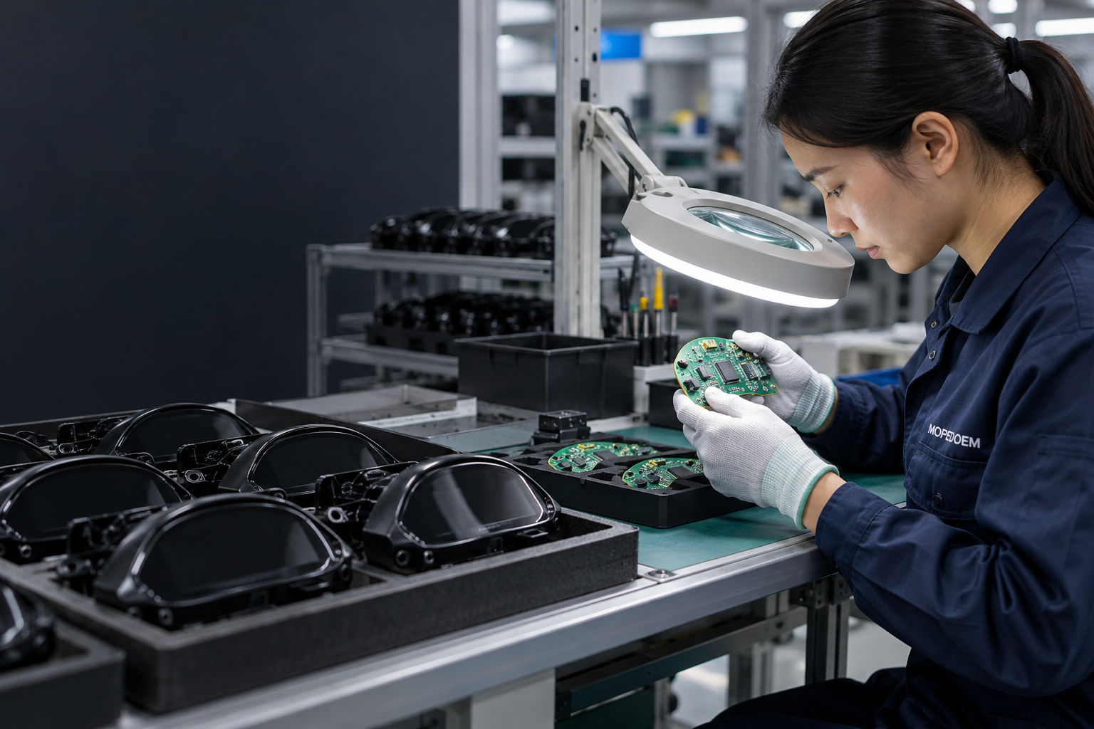
How electronic instrument clusters are madeElectric two-wheelers · Electronic instrument clusters
MOPEDOEM · Back to production partners

Four main stages · General process illustration

From circuitry,
to clear vehicle information.

Enter the workshop and follow the process. Scroll down to see the scene and manufacturing points at each stage.

General manufacturing illustration · Not a record from a partner supplier’s site

AI-generated photographic-style illustration · Not an on-site photographic record

Electronic instrument clusters · Process imageryPHOTOGRAPHIC PROCESS STUDY · AI GENERATED

Four main stages. Expand each one to review the process details.

Choose a stage to enter its chapter. Every image is an AI-generated photographic-style illustration; process parameters follow the actual work instructions.

Written process guide

Generic process illustrations, not evidence of a factory owned by our company. Actual work instructions and acceptance requirements must be confirmed for the order.

Circuit boards and incoming inspection

Verify the display components, housing and circuit board revisions, then complete applicable assembly and soldering checks.

  1. Identify the display type and software and hardware revisions. Verify incoming parts against the approved bill of materials.
  2. Populate and solder components as required by the selected circuit-board process, using the specified electrostatic discharge protection.
  3. Check solder joints, polarity and connections according to the inspection plan. Production yield cannot be inferred from an illustration.
Display module and bezel assembly

Fit the screen and applicable light guides or backlights for the display design, then fit the housing and transparent window.

  1. Protect the display surface, ribbon cable and terminals. Check for particles, scratches and cosmetic defects as specified.
  2. Install the module and applicable optical components for the specific display design without pinching the ribbon cable.
  3. Check mounting position, housing clearances and the visible display area. Not every cluster has the same layer stack.
Software configuration and integrated functional testing

Use the approved version for applicable configuration and verify display and communications with a compatible test interface.

  1. If flashing or configuration is required, use the approved version and record it. Do not make unauthorized changes to vehicle display parameters.
  2. Check applicable displays, indicators and buttons against the model's signals. Test data is not a product commitment.
  3. Verify protocol, pinout and fault response against the actual controller or a validated simulator. Record issues and retest.
Final assembly, inspection and packing

Check the housing, window, connector and final configuration. Protect and box the unit according to the order requirements.

  1. Check sealing, harness exits and assembly completeness for the design. Do not claim an ingress protection rating based on appearance alone.
  2. Perform the required functional, visual and other verification under the actual cluster inspection plan. Confirm that all anomalies have been resolved.
  3. Protect the window and interfaces. Verify the revision, identification and accompanying materials, and maintain batch traceability.

    Images are AI-generated process illustrations, not actual factory photographs. Clicking a step displays an explanation; it does not mean equipment in the image is playing the corresponding action.