How hub motors are madeElectric two-wheelers · Hub motors
MOPEDOEM · Back to production partners

Four main stages · General process illustration

From copper wire and magnetic fields,
to drive inside the wheel.

Enter the workshop and follow the process. Scroll down to see the scene and manufacturing points at each stage.

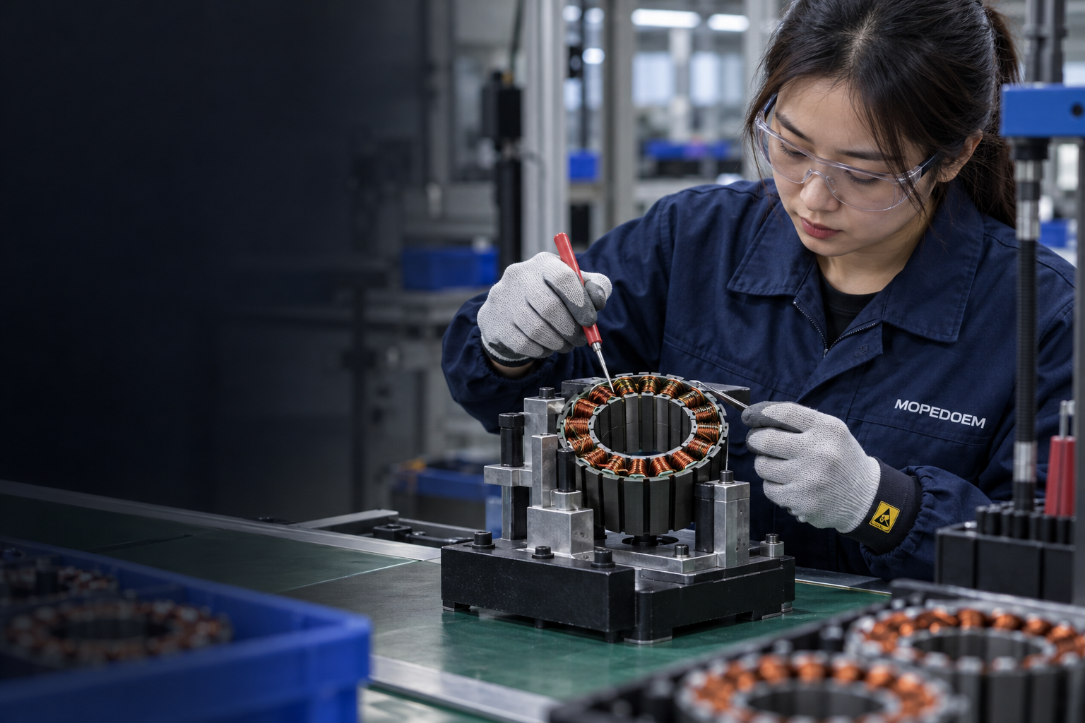
General manufacturing illustration · Not a record from a partner supplier’s site

AI-generated photographic-style illustration · Not an on-site photographic record

Hub motors · Process imageryPHOTOGRAPHIC PROCESS STUDY · AI GENERATED

Four main stages. Expand each one to review the process details.

Choose a stage to enter its chapter. Every image is an AI-generated photographic-style illustration; process parameters follow the actual work instructions.

Written process guide

Generic process illustrations, not evidence of a factory owned by our company. Actual work instructions and acceptance requirements must be confirmed for the order.

Incoming stator inspection, winding and insulation

Check the stator core and insulating materials, then wind and inspect the coils according to the design.

  1. Inspect applicable incoming parts, such as the stator core, slot insulation and shaft. Verify their construction against the drawings.
  2. Wind the coils and connect the leads as designed, protecting the enamelled wire and slot insulation. Schedule varnish impregnation or other treatments as the actual process requires.
  3. Check winding connections and specified insulation characteristics according to the inspection plan. Do not assume a turn count, wire diameter or electrical limit.
Rotor hub and permanent magnet assembly

Inspect the hub housing and magnets, position and secure them as designed, and complete any necessary follow-up treatment.

  1. Verify the housing, magnets and applicable materials against the drawings. Handle magnetic parts according to workstation safety requirements.
  2. Verify magnet orientation, position and retention as designed. Adhesive bonding and other retention methods are not freely interchangeable.
  3. Check retention and geometry. Perform any required curing and verification according to the approved process; there is no universal magnet count or temperature.
Bearings, sensors and final assembly

Assemble the stator, rotor, bearings and end covers as required by the design. Protect the leads and check rotation.

  1. Fit the bearings and required sensors for the specific design. Do not assume all motors use the same Hall sensor configuration.
  2. Use suitable fixtures to control magnetic attraction and assembly fit, avoiding impact and pinch hazards.
  3. Check the lead exit, end covers and rotation against the drawings. Confirm sealing and the brake interface for the actual model.
Controlled testing, identification and packing

Perform applicable electrical, operational and performance tests under the product plan. Review the results before protective packing.

  1. Secure the motor at a guarded workstation. Qualified personnel should operate a compatible test setup according to procedure.
  2. Perform applicable electrical, speed, noise or load checks according to the plan. An illustrated test bench does not prove that inspection was passed.
  3. Resolve anomalies and retest. Verify the model, batch and leads, and protect shaft ends and interfaces before boxing.

    Images are AI-generated process illustrations, not actual factory photographs. Clicking a step displays an explanation; it does not mean equipment in the image is playing the corresponding action.